
BURSTER PRÄZISIONSMESSTECHNIK GMBH & CO KG
Germany

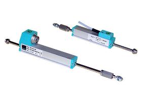
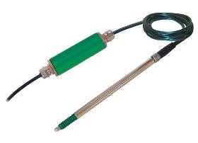
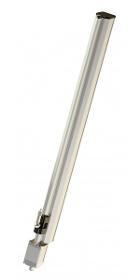
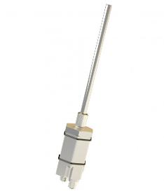
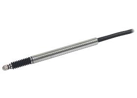
Due to its high resolution also when measuring long distances, linear displacement measurements up to 900 mm can be carried out. Conversions between rotatory and translation movements through ball screws, wire or cord connections and so on are not necessary for direct displacement measurement. Application fields include: —Electromagnets —Deformations - bending —Pneumatic cylinders —Length tolerances —Press-insertions (longitudinal press-fits) —Feed strokes —Machine hubs —Punch, knee lever or extruder distances —Hydraulic cylinders Due to the technology employed in potentiometric displacement sensors, they always operate with a sliding contact system. Special processes are applied to give the resistance tracks low friction, low tendency to stick/slip, resistance to abrasion and long-term stability. The rod is guided in a low-play floating frontal bearing. This absorbs small angular and parallel displacements.
BURSTER PRÄZISIONSMESSTECHNIK GMBH & CO KG
Germany
The high resolution allows linear measurements to be accurately sized even in large measurement ranges. Conversion of rotatory and translational motion by spindles, wires or others is not necessary for direct displacement measurement. Areas of application are: —Hydraulic and pneumatic cylinders —Detection of positions on coordinate —Inspection machines —Displacement of plungers, knee levers or extruders —Coil and de coil lengths —Strokes on chassis —Metering strokes Displacement sensors model 8718, using a resistance track made of conductive plastic material, are suitable for direct, accurate and absolute measurements of displacements and lengths. Special processes are applied to give the resistance tracks low friction, low tendency to stick/slip, resistance to abrasion and long-term stability. The vibration-cushioned slider allows a clear signal output even by slight shocks or high operating speeds up to 10 m/s.
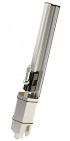
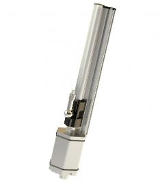
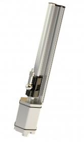
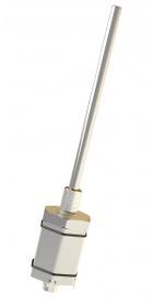
BURSTER PRÄZISIONSMESSTECHNIK GMBH & CO KG
Germany
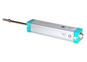
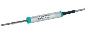
Displacement sensors models 8710 and 8711 with resistance tracks made of conductive plastic material are designed for a direct and accurate measuring of mechanical displacements. A special ball joint coupling is mountable on both ends of the driving rod. Because of this the sensor may be used free of clearance or lateral forces also with angular or parallel misalignment between sensor and measuring device. A special multi-fingered slider provides a good electrical contact also at high adjustment speeds or vibrations. Areas of application are: —Electromagnets —Switch and button deflections —Pneumatic cylinders —Press-fits (longitudinal press-fits) —Hydraulic cylinders —Measurements of deformation and bending —Length tolerances —Feeding paths Due to the technology employed in potentiometric displacement sensors, they always operate with a sliding contact system.
MICRO-EPSILON MESSTECHNIK GMBH & CO. KG
Germany
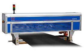
The system RTP 8301.EO operates according to a combination principle consisting of a thru-beam sensor, an eddy current sensor and a measuring roller. The eddy current sensor and the thru-beam sensor are applied on an innovative measuring clamp. Since the sensor measures the distance from the clamp to the roller, the lower side of the material is detected. As the sensor performance is specially aligned with the measuring task a huge measuring gap is possible while offering highest precision. The thru-beam sensor detects the upper side of the material. The thickness of the target is the difference between the two signals. The measuring clamp is equipped with a pneumatically cleaning mechanism and therefore ideal for the application in harsh environment. The profilometer corresponds to the TIP 8301 regarding its functionality. However, it has a different operators´ frontend and evaluation functions.
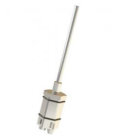
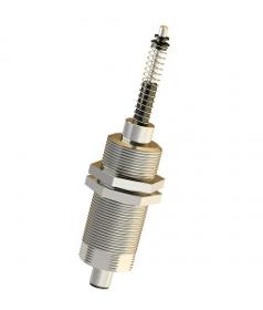
BURSTER PRÄZISIONSMESSTECHNIK GMBH & CO KG
Germany
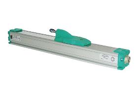
Potentiometric displacement sensors are used for direct, precise measurement of mechanical displacements. The mechanical parts of the measuring equipment must be set-up in such a way that the sliding shaft can move without play or lateral forces. A special multi-finger slider ensures good contact even when the adjustment speed is high or in the presence of vibration. With its housing diameter of only 12.7 mm, the model 8709 is also suitable for highly compact structures. The movable fastening clamps allow the user variable options for attaching the sensor without complication. Optionally available adaptations, such as flange and ball joint versions, extend and complement the range of possible applications. Typical fields of application include: Measuring the stroke on riveting machines Measuring insertion distances Offset measurements on bearings Spring travel measurements on axes Measurements of the movement of hoisting platforms Length measurements on pipe bending machines
BURSTER PRÄZISIONSMESSTECHNIK GMBH & CO KG
Germany
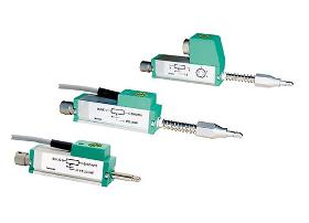
Inductive displacement sensors using the principle of the differential transformer (LVDT) can be used to measure displacement and, indirectly, magnitudes that can be converted into displacements such as force, pressure, strain, torque, vibration and so forth. Thanks to the high quality of their measurements, their high protection and long service life, these sensors are used in many technologies (industry, research, development, etc.). Applications include measuring, controlling, regulating and monitoring both slow and fast movements between machine parts, measurements of position and positional changes of components and structural foundations, servo regulators, valve and robot controllers, growth measurements and so on. Their design is robust - the internal coils and electronics are potted - as a result of which the sensors can easily withstand shock and vibration.
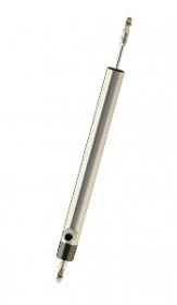
BURSTER PRÄZISIONSMESSTECHNIK GMBH & CO KG
Germany
Inductive displacement sensors of this series measure linear displacements and indirectly all mechanical values convertible into displacements by additional equipment (i.e. tension and compression forces, extension, torque, vibration). The sensor body equipped with a connector has an outer diameter of only 8 mm and therefore is especially well suitable for the integration in dimensionally restricted structures. Typical application fields are displacement and extension measurements on: —Machines —Servo systems —Motor vehicles —Test benches —Production plants The cylindrical case made of stainless steel, houses a differential transformer (LVDT). It consists of a primary and two secondary coils with axially moveable core. A displacement of this core changes the magnetic induction of the coils. The INLINE carrier frequency amplifier converts the displacement into a direct proportional electrical DC voltage.
TWK-ELEKTRONIK GMBH
Germany
The displacement transducers work according to the principle of the differential choke (inductive half bridges). They consist of two coils which are encapsulated in a Mu metal cylinder in a sealed and vibration-proof manner. A Mu-metal plunger causes an opposite induction change in the two coils when displaced by the hollow coil body. The displacement transducers are designed for an oscillator frequency of 10 kHz. Power supply and signal conditioning are provided by external module modules.

TWK-ELEKTRONIK GMBH
Germany
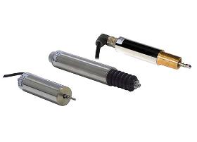
The displacement transducers operate according to the principle of run time measurement between two points of a magnetostrictive waveguide. One point is determined by a moveable position magnet, whose distance from the null point corresponds to the section to be measured. The run time of an emitted impulse is directly proportionate to this section. Conversion to an analogue measuring signal takes place in the downstream electronics. The waveguide is housed in a pressure-resistant stainless steel tube or extruded profile. To the rear of this is a die-cast aluminium housing containing the electronics in SMD technology. Electrical connection is implemented via a circular connector. In the rod version, the position magnet is located in a ring, which is guided over the rod without contact. In the profile version, it is located either in a slider, which is linked to the moving part of the machine via a ball joint, or it moves as a liftable position magnet, without wear, over the profile.
TWK-ELEKTRONIK GMBH
Germany
The displacement transducers operate according to the principle of run time measurement between two points of a magnetostrictive waveguide. One point is determined by a moveable position ring, whose distance from the null point corresponds to the section to be measured. The run time of an emitted impulse is directly proportionate to this section. Conversion to a displacement signal takes place in the downstream electronics. The waveguide is housed in a pressure-resistant stainless steel tube or extruded profile. To the rear of this is a die-cast aluminium housing containing the electronics in SMD technology. In the rod version, the position magnet is located in a ring, which is guided over the rod without contact. In the profile version, it is located either in a slider, which is linked to the moving part of the machine via a ball joint, or it moves as a liftable position magnet, without wear, over the profile.
TWK-ELEKTRONIK GMBH
Germany
The displacement transducers operate according to the principle of run time measurement between two points of a magnetostrictive waveguide. One point is determined by a moveable position magnet, whose distance from the null point corresponds to the section to be measured. The run time of an emitted impulse is directly proportionate to this section. Conversion to a digital measuring signal takes place in the downstream electronics. The waveguide is housed in a pressure-resistant stainless steel tube or extruded profile. To the rear of this is a die-cast aluminium housing containing the electronics in SMD technology. In the rod version, the position magnet is located in a ring, which is guided over the rod without contact. In the profile version, it is located either in a slider, which is linked to the moving part of the machine via a ball joint, or it moves as a liftable position magnet, without wear, over the profile.
TWK-ELEKTRONIK GMBH
Germany
The displacement transducers work according to the principle of the differential choke (inductive half bridges). They consist of two coils which are encapsulated in a Mu metal cylinder in a sealed and vibration-proof manner. A Mu-metal plunger causes an opposite induction change in the two coils when displaced by the hollow coil body. The displacement transducers are designed for an oscillator frequency of 10 kHz. Power supply and signal conditioning are provided by external module modules.
TWK-ELEKTRONIK GMBH
Germany
The displacement transducers operate according to the principle of run time measurement between two points of a magnetostrictive waveguide. One point is determined by a moveable position magnet, whose distance from the null point corresponds to the section to be measured. The run time of an emitted impulse is directly proportionate to this section. Conversion to an analogue measuring signal takes place in the downstream electronics. The waveguide is housed in an extruded aluminium profile. The electronics is housed in a die-cast aluminium sensor head. Electrical connection is implemented via a circular connector. The position magnet is located either in a slider, which is linked to the moving part of the machine via a ball joint, or it moves as a liftable position magnet, without wear, over the profile.
TWK-ELEKTRONIK GMBH
Germany
The displacement transducers operate according to the principle of run time measurement between two points of a magnetostrictive waveguide. One point is determined by a moveable position magnet, whose distance from the null point corresponds to the section to be measured. The run time of an emitted impulse is directly proportionate to this section. Conversion to a digital measuring signal takes place in the downstream electronics. The waveguide is housed in a pressure-resistant stainless steel tube or extruded profile. To the rear of this is a die-cast aluminium housing containing the electronics in SMD technology. In the rod version, the position magnet is located in a ring, which is guided over the rod without contact. In the profile version, it is located either in a slider, which is linked to the moving part of the machine via a ball joint, or it moves as a liftable position magnet, without wear, over the profile.
TWK-ELEKTRONIK GMBH
Germany
The displacement transducers operate according to the principle of run time measurement between two points of a magnetostrictive waveguide. One point is determined by a moveable position ring, whose distance from the null point corresponds to the section to be measured. The run time of an emitted impulse is directly proportionate to this section. Conversion to a displacement signal takes place in the downstream electronics. The waveguide is housed in a pressure-resistant stainless steel tube or extruded profile. To the rear of this is a die-cast aluminium housing containing the electronics in SMD technology. In the rod version, the position magnet is located in a ring, which is guided over the rod without contact. In the profile version, it is located either in a slider, which is linked to the moving part of the machine via a ball joint, or it moves as a liftable position magnet, without wear, over the profile.

TWK-ELEKTRONIK GMBH
Germany
The displacement transducers operate according to the principle of run time measurement between two points of a magnetostrictive waveguide. One point is determined by a moveable position magnet, whose distance from the null point corresponds to the section to be measured. The run time of an emitted impulse is directly proportionate to this section. Conversion to a measuring signal takes place in the downstream electronics. The waveguide is housed in a pressure-resistant stainless steel tube or extruded profile. To the rear of this is a die-cast aluminium housing containing the electronics in SMD technology. In the rod version, the position magnet is located in a ring, which is guided over the rod without contact. In the profile version, it is located either in a slider, which is linked to the moving part of the machine via a ball joint, or it moves as a liftable position magnet, without wear, over the profile.
TWK-ELEKTRONIK GMBH
Germany
The displacement transducers operate according to the principle of run time measurement between two points of a magnetostrictive waveguide. One point is determined by a moveable position magnet, whose distance from the null point corresponds to the section to be measured. The run time of an emitted impulse is directly proportionate to this section. Conversion to an analogue measuring signal takes place in the downstream electronics. The waveguide is housed in a pressure-resistant stainless steel tube or extruded profile. To the rear of this is a die-cast aluminium housing containing the electronics in SMD technology. Electrical connection is implemented via a circular connector. In the rod version, the position magnet is located in a ring, which is guided over the rod without contact. In the profile version, it is located either in a slider, which is linked to the moving part of the machine via a ball joint, or it moves as a liftable position magnet, without wear, over the profile.

Do you sell or make similar products?
Sign up to europages and have your products listed

TWK-ELEKTRONIK GMBH
Germany
The displacement transducers operate according to the principle of run time measurement between two points of a magnetostrictive waveguide. One point is determined by a moveable position magnet, whose distance from the null point corresponds to the section to be measured. The run time of an emitted impulse is directly proportionate to this section. Conversion to a digital measuring signal takes place in the downstream electronics. The waveguide is housed in a pressure-resistant stainless steel tube or extruded profile. To the rear of this is a die-cast aluminium housing containing the electronics in SMD technology. Electrical connection is implemented via a circular connector. In the rod version, the position magnet is located in a ring, which is guided over the rod without contact. In the profile version, it is located either in a slider, which is linked to the moving part of the machine via a ball joint, or it moves as a liftable position magnet, without wear, over the profile
TWK-ELEKTRONIK GMBH
Germany
The displacement transducers operate according to the principle of run time measurement between two points of a magnetostrictive waveguide. One point is determined by a moveable position magnet, whose distance from the null point corresponds to the section to be measured. The run time of an emitted impulse is directly proportionate to this section. Conversion to a digital measuring signal takes place in the downstream electronics. The waveguide is housed in a pressure-resistant stainless steel tube or extruded profile. To the rear of this is a die-cast aluminium housing containing the electronics in SMD technology. Electrical connection is implemented via a circular connector. In the rod version, the position magnet is located in a ring, which is guided over the rod without contact. In the profile version, it is located either in a slider, which is linked to the moving part of the machine via a ball joint, or it moves as a liftable position magnet, without wear, over the profile.
TWK-ELEKTRONIK GMBH
Germany
The displacement transducers operate according to the principle of run time measurement between two points of a magnetostrictive waveguide. One point is determined by a moveable position magnet, whose distance from the null point corresponds to the section to be measured. The run time of an emitted impulse is directly proportionate to this section. Conversion to an analogue measuring signal takes place in the downstream electronics. The waveguide is housed in a pressure-resistant stainless steel tube or extruded profile. To the rear of this is a die-cast aluminium housing containing the electronics in SMD technology. Electrical connection is implemented via a circular connector. In the rod version, the position magnet is located in a ring, which is guided over the rod without contact. In the profile version, it is located either in a slider, which is linked to the moving part of the machine via a ball joint, or it moves as a liftable position magnet, without wear, over the profile.
TWK-ELEKTRONIK GMBH
Germany
The displacement transducers work according to the principle of the differential choke (inductive half bridges). They consist of two coils which are encapsulated in a Mu metal cylinder in a sealed and vibration-proof manner. A Mu-metal plunger causes an opposite induction change in the two coils when displaced by the hollow coil body. The displacement transducers are designed for an oscillator frequency of 10 kHz. Power supply and signal conditioning are provided by external module modules.

TWK-ELEKTRONIK GMBH
Germany
The displacement transducers operate according to the principle of run time measurement between two points of a magnetostrictive waveguide. One point is determined by a moveable position magnet, whose distance from the null point corresponds to the section to be measured. The run time of an emitted impulse is directly proportionate to this section. Conversion to an analogue measuring signal takes place in the downstream electronics. The waveguide is housed in a pressure-resistant stainless steel tube or extruded profile. To the rear of this is a die-cast aluminium housing containing the electronics in SMD technology. Electrical connection is implemented via a circular connector. In the rod version, the position magnet is located in a ring, which is guided over the rod without contact. In the profile version, it is located either in a slider, which is linked to the moving part of the machine via a ball joint, or it moves as a liftable position magnet, without wear, over the profile.
FERNSTEUERGERÄTE KURT OELSCH GMBH
Germany
Rope Length Transmitter with high precision analog or digital encoders The determination of measuring lengths in the range of one up to several meters is preferably carried out by using well priced and easy-tomount transducers on the basis of the draw wire measuring principle. In connection with measuring problems of industrial applications e.g. on - cranes, drilling machines and excavators - pressing, punching and injection moulding machines - weirs and lock gates - multilevel shelving rack systems and theatre stages - wood- and stone-working machines and also in - instrument engineering, high-tech medical devices etc. Rope length measuring systems series SL 3000 have proven for years to be very reliable, capable of measuring lengths up to 40 m with high accuracy and reliability even in extremely dusty and moist atmospheres.
EDDYLAB GMBH
Germany
High-quality eddy current probes: Beside robustness, high dynamics and high resolution the TX-Series also stands out with a wide temperature range from -60 °C up to 180 °C. ■ High precision measurement ■ High resolution (submicrometer) ■ High dynamics (124 kSa/s) ■ Minimal temperature coefficient ■ High noise immunity ■ Custom-made probes
BURSTER PRÄZISIONSMESSTECHNIK GMBH & CO KG
Germany
These displacement sensors are potentiometric displacement sensors used for direct measurement, testing and monitoring of mechanical displacements. The spring-loaded control rod eliminates the need of coupling with the measurement object. A prerequisite for a very long life duration of the devices is a parallel alignment of the motion direction of the measurement object and the rod. Areas of application are: Displacement on: —Electromagnets —Hydraulic cylinders —Switches and buttons Measurements of: —Deformation —Bending —Press-fits —Feed strokes Due to the technology employed in potentiometric displacement sensors, they always operate with a sliding contact system. FEATURES: —Measurement ranges: 0 ... 10 mm to 0 ... 150 mm —Non-linearity up to 0.05 % F.S. —Resolution 0.01 mm —Follower roll on request —Optional with internal spring
BURSTER PRÄZISIONSMESSTECHNIK GMBH & CO KG
Germany
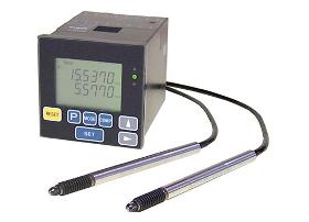
The incremental digital displays are used in combination with our high-precision displacement sensors 8738. The digital technology of these measuring systems satisfies high demands for precision and long service life, as is required more and more nowadays — in measuring laboratories — in production — in testing laboratories — in workshops and many other areas. Typical uses: —Automatic assembly machines —Semiconductor industry —Keyboard tests —Robot controllers —Testing of shafts and planes —Measurement of differential displacement With its phenomenal resolution of 0.1 µm and the high response frequency of 20 MHz, the 9140 is a powerful display unit with a compact design. The comparator function integrated as standard allows for direct evaluation of measurements almost in real-time; these can be processed further by a higher-level controller. A rather more comprehensive acquisition method is also integrated into the system.
BURSTER PRÄZISIONSMESSTECHNIK GMBH & CO KG
Germany
Incremental magnetic measuring heads offer maximum precision over the full range of measurements. As a result of the magnetic operating principle and the robust mechanical construction, they are insensitive to soiling and are therefore ideally suited to use in production facilities. Thanks to the high quality of their measurements, their high protection and long service life, these sensors are used in many technologies (industry, research, development etc.). Typical applications include: —Monitoring both slow and fast movements between machine parts —Measurements of position and positional changes in components and structural foundations, of servo regulators, valve and robot controllers —Measurement of growth, and so on The incremental displacement sensors are based on a magnetic principle: consisting of a magnetic scale and a multi-slot reading head that responds to changes in magnetic flux, they detect linear movements with high precision and resolution.
Results for
Displacement sensor - Import exportNumber of results
71 ProductsCountries
Company type